
- drow the flow chart of project and flow chart of Digital pH Meter.
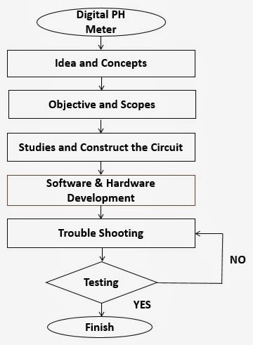
flow chart of the project

flow chart of pH meter
pH meter block diagram


In this project, the circuit
requires a 5-volt DC power source. The main input of power supply can be use DC
adapter device or battery device. The range of input power supply is between
9-volt until 12-volt to make sure the voltage regulators can provide a stable
and accurate 5-volt power source for the two op amp, temperature circuit, pic
circuit, and also LCD display circuit. Refer the figure below, the D1 is use to
protect the circuit from wrong polarity supply. C1 and C2 is use to stabilize
the voltage at the input side of the LM7805 voltage regulator, while the C3 and
C4 is use to stabilize the voltage output side of the LM7805 voltage supply.
LED is a RED to indicate the power status of the circuit. R1 is resistor to
protect LED from over current that will burn the LED.
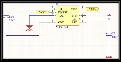
An addition, the pH meter
circuit requires a 5-volt DC power source supplied from the dual positive and
negative power supply circuit. The positive power supply is providing by the
voltage regulator LM7805 component. Otherwise, the negative power supply is
providing by the output voltage from ICL7660s component. The negative power
supply circuit shown in figure below. We use ICL7660s because the device are
monolithic CMOS power supply circuits with offer unique performance advantages
over previously available devices. The ICL7660s performs supply voltage
conversions from positive to negative for an input range of +1.5v to +10.0v
resulting in complementary output voltages of -1.5v to -10.0v.
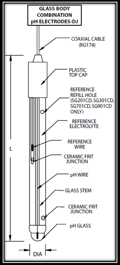
pH glass electrode
SENSING
PROBE
The sensing probe is a glass
electrode with two electrodes in built in it. The glass probe acts as a sensing
part of the pH meter; it is actually a galvanic cell which converts the change
in hydrogen ion concentration to a corresponding change in voltage. The sensing
probe should be immersed in the solution whose pH is to be measured.
A glass electrode is a type
of ion-selective electrode made of a doped glass membrane that is sensitive to
a specific ion. It is an important part of the instrumentation for chemical
analysis and physic- chemical studies. A typical modern pH probe is a
combination electrode, which combines both the glass and reference electrodes
into one body. The combination electrode consist of the following parts (refer
figure):-
1. A
sensing part of electrode, a bulb made from a specific glass.
3. Internal
solution, usually a pH=7 buffered solution of 0.1 mol/KCL for pH electrodes or
0.1 mol/L MeC1 for pMe electrodes.
4. When
using the silver chloride electrode, a small amount of AgC1 can precipitate
inside the glass electrode.
5. Reference
electrode, usually the same type as 2
6. Reference
internal solution, usually 0.1 mol/L KCL
7. Junction
with studied solution usually made from ceramics or capillary with asbestos or
quartz fiber.
8. Body
of electrode, made from non-conductive glass or plastics.
The bottom of a pH electrode
balloons out into a round thin glass bulb. The pH electrode is best thought of
as a tube within a tube. The inside most tube (inner tube) contains an
unchanging mol/L
HCL solution. Also inside the inner tube is the cathode terminus of the
reference probe. The anodic terminus wraps itself around the inside of the
inner tube. It is filled with a reference solution of 0.1 mol /L KCL and has
contact with the solution on the outside of the pH probe by us plug that serves
as a salt bridge.
The value of voltage
produced by the probe is fortunately a linear function of the pH. For example,
at pH 7.00, the probe produce 0 volts while at pH 6.00, it produces +0.06 volts
or +60 millivolts. Notice the positive polarity mark; if the voltage were of
negative polarity, the meter pointer would go to the pH reading of 8.00.
Generally, a probe will produce about 60 millivolts for each change of 1 pH
unit. The theoretical output of standard Ag/AgCl pH probe is 59.16 mV /pH at 25⁰C with 0 volts out at
a pH of 7.00.

Using an ultralow input
current amplifier, a CMOS micro power op-amp, and a digital multi meter, you
can construct a useful pH meter. The signal from a pH probe has a typical
resistance between 10 mega ohms and 1000 mega ohms. Because of this is high
value input impedance, it is very important that the amplifier input currents
be as small as possible. The LMC6001, with the less than 25fA input current, in
an ideal choice for this pH meter circuit.
The ultralow input current
amplifier, the LMC6001, amplifies the probe output providing a scaled voltage
of +/- 100mV/pH from a pH 7. Overall gain adjustments to the pH meter can be
made via trimmer at PH 1. Hence, a buffer amplifier is used between the sensing
probe and the following amplifier stages. LMC6001 is used in the amplifier as
it having impedance in the range of terra ohms.
AMPLIFIER
Several amplifier stages are
used for the purpose of boosting the voltage output from the sensing probe. The
second op- amp, a micro power LMC6041, provides phase inversion and offset so
that the output is directly proportional to the pH value, over the full range
of the pH probe. The range of output providing by the LMC6041 is between 0 volt
to 1.4 volt means that 0 until 14 ph.
Offset circuit, consists of
a zener diode, two resistors, and the trimmer at PH 2. The output of LMC6041
can be directly coupled to a digital multi meter or converting into the analog
to digital value using the PIC to display value in the digital value, that
means can be calibrated to read
LCD DISPLAY

lcd display connection
The display unit used is an
HD44780 LCD or LCD display 16x2. It is the final block and it displays the pH
of the solution digitally and also displays the temperature value digitally.
This LCD can be operated in two different modes, 4 bit mode and 8 bit mode.
In 8 bit mode, pins 7-14 of the LCD are
connected to eight Inputs/ output pins on the microcontroller. While in 4 bit
mode, pins 11-14 on the LCD are connected to four inputs/ output pins on the
microcontroller. The advantage to operating in 8 bit mode is that the
programming is a bit simpler and data can be updated more quickly. The obvious
reason to operate in 4 bit mode is to save four inputs/ output pins on the PIC
microcontroller
